

Inside an FRC robot
Every robot comes from three subteams working at once. Here are the real tools, parts, wiring and code we use, so you know exactly what you’d be doing on the team.
- Robot weight
- 115 lb
- Frame perimeter
- 110 in
- Starting height
- 30 in
- Battery
- 12 V
Limits from the 2026 game manual. FIRST updates them every season at kickoff.
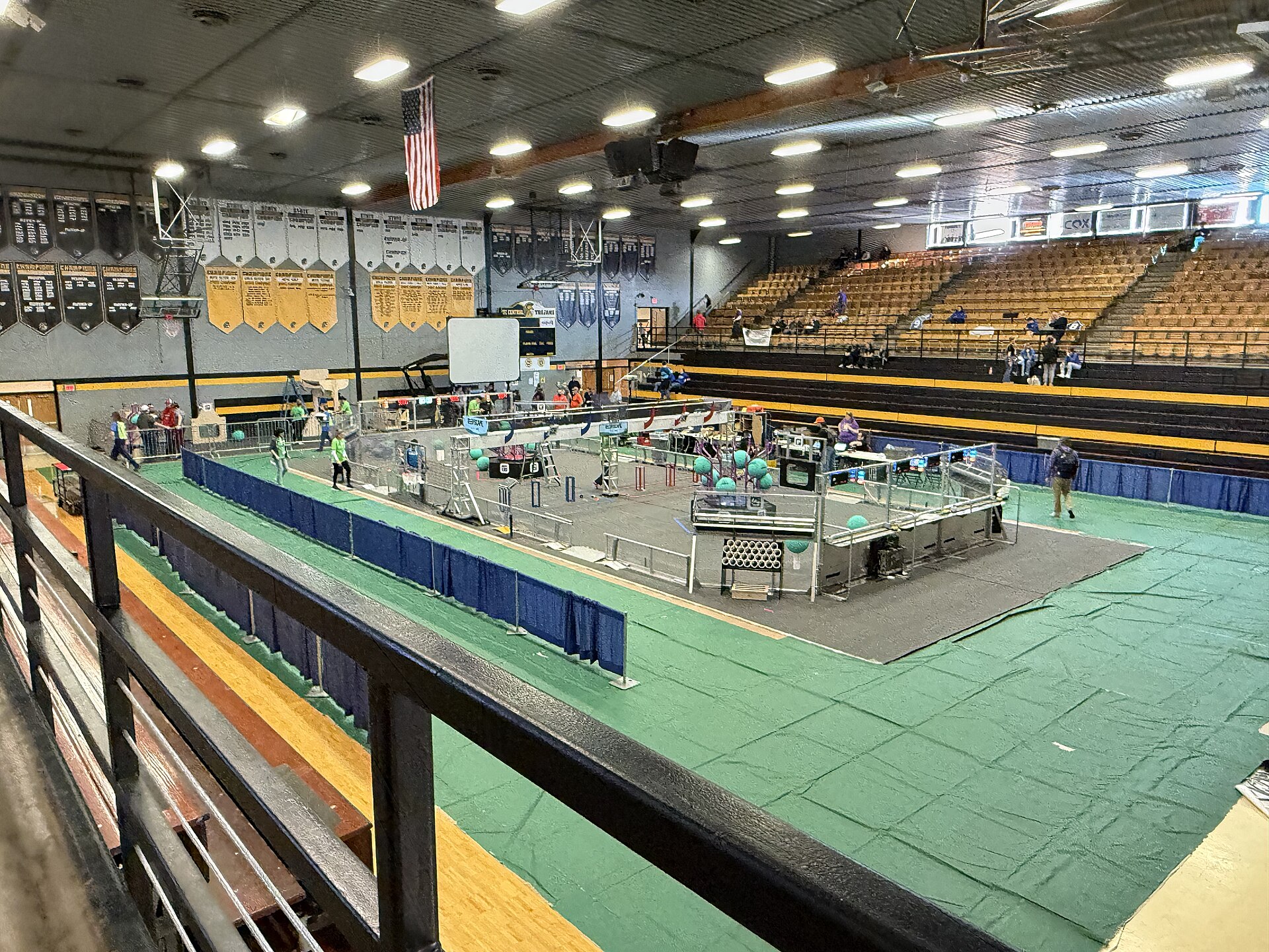
Design it, build it, break it, fix it
Mechanical turns the game into a machine: a drivetrain to move, mechanisms to score, and a frame that survives full-speed hits.
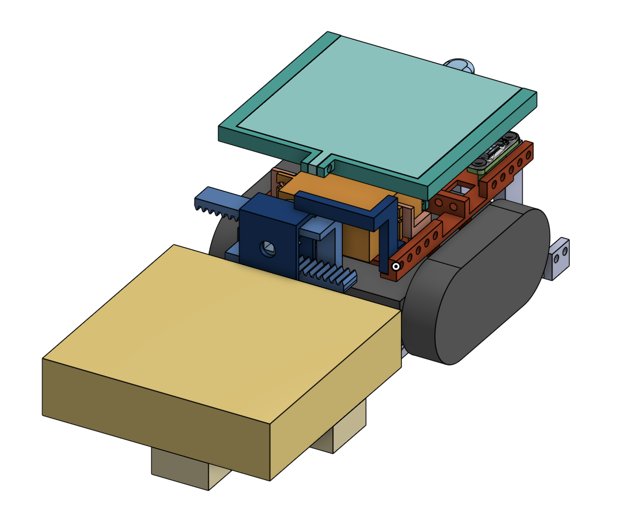
Every part exists on screen before it’s cut
We design in Onshape, professional CAD that runs in a browser and is free for FIRST teams. Everyone can work on the same robot at once, and every change is saved in its history.
You sketch a part in 2D, extrude it into 3D, then put parts together in an assembly to check clearances and motion. Plates export straight to the CNC router; tube gets a drawing with every hole marked.
Other teams use SolidWorks or Fusion. The skills transfer: it’s the same ideas of sketches, features and assemblies.
- 01
Strategy
Read the manual and decide what the robot must do, and what it will skip.
- 02
Sketch
Whiteboard ideas, then rough geometry: reach, heights, angles.
- 03
Prototype
Wood, polycarb and drills. Prove a mechanism works before it’s pretty.
- 04
CAD
Model every part and the whole robot so it all fits before anything is cut.
- 05
Manufacture
Cut, drill, CNC and 3D print parts from the CAD, then assemble.
- 06
Test & iterate
Drive it, break it, find out why, and make version two.
Swerve: every wheel steers on its own
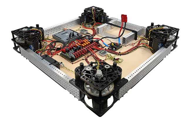
Most competitive robots now use swerve drive. Each corner has a module with two motors: one spins the wheel, the other turns it. The robot can drive any direction while facing any other direction.
Teams buy modules off the shelf from vendors like Swerve Drive Specialties, West Coast Products or REV, then build the frame around them. A simpler tank drive (wheels on each side, like a tank) is a great first drivetrain and much easier to program.
What a robot is made of
Frame & structure
6061 aluminum box tube, usually 2×1 in with 1/16 or 1/8 in walls. Light, stiff and easy to drill.
Plates & guards
Aluminum plate for gussets and gearbox plates, polycarbonate where parts need to flex or be seen through.
Power transmission
1/2 in hex shafts, bearings, gears, belts and chain. Gear ratios trade speed for torque.
Fasteners
#10-32 bolts with nylon-insert lock nuts, and 3/16 in aluminum rivets for frames that stay put.
3D printed parts
PETG, nylon and carbon-fiber nylon for spacers, brackets and custom shapes that would take hours to machine.
Motors
Brushless motors such as the Kraken X60 and NEO Vortex, each driven by its own motor controller.
How fast will it drive?
Gear ratios are where mechanical meets physics. A motor spins about 6,000 RPM with no load, far too fast for a wheel, so a gearbox slows it down and multiplies the torque.
- Motor free speed6,000 RPM
- ÷ 6.75 : 1 gear ratio889 RPM at the wheel
- × 4 in wheel (π × 4 = 12.6 in per turn)≈ 15.5 ft/s
- Real world, with friction and weight≈ 12–13 ft/s
The parts that actually play the game
- Drivetrain. Swerve or tank. Moves the robot and takes every hit.
- Intake. Rollers with soft, grippy wheels pull game pieces off the floor.
- Elevator. Stages on bearings, lifted by belts or rope, to reach high goals.
- Arm / pivot. A heavily geared joint that swings a scorer into position.
- Shooter. Flywheels spun to an exact speed so every shot lands the same way.
- Climber. Hooks and winches that lift the robot at the end of a match.
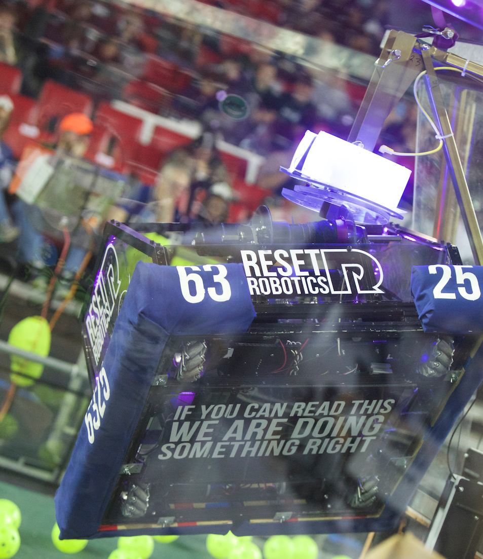
- Bumpers. Required padding of pool noodles on a plywood backing, covered in red or blue fabric, so robots can hit each other safely.
Tools you’ll learn to use
- Bandsaw and miter saw for cutting tube to length
- Drill press and hand drills for holes, rivets and bolts
- CNC router for aluminum and polycarbonate plates from CAD
- 3D printers for brackets, spacers and prototypes
- Lathe and mill for shafts, spacers and precision parts
- Safety glasses on, every time, for everyone in the shop
Power, protection and a lot of wire
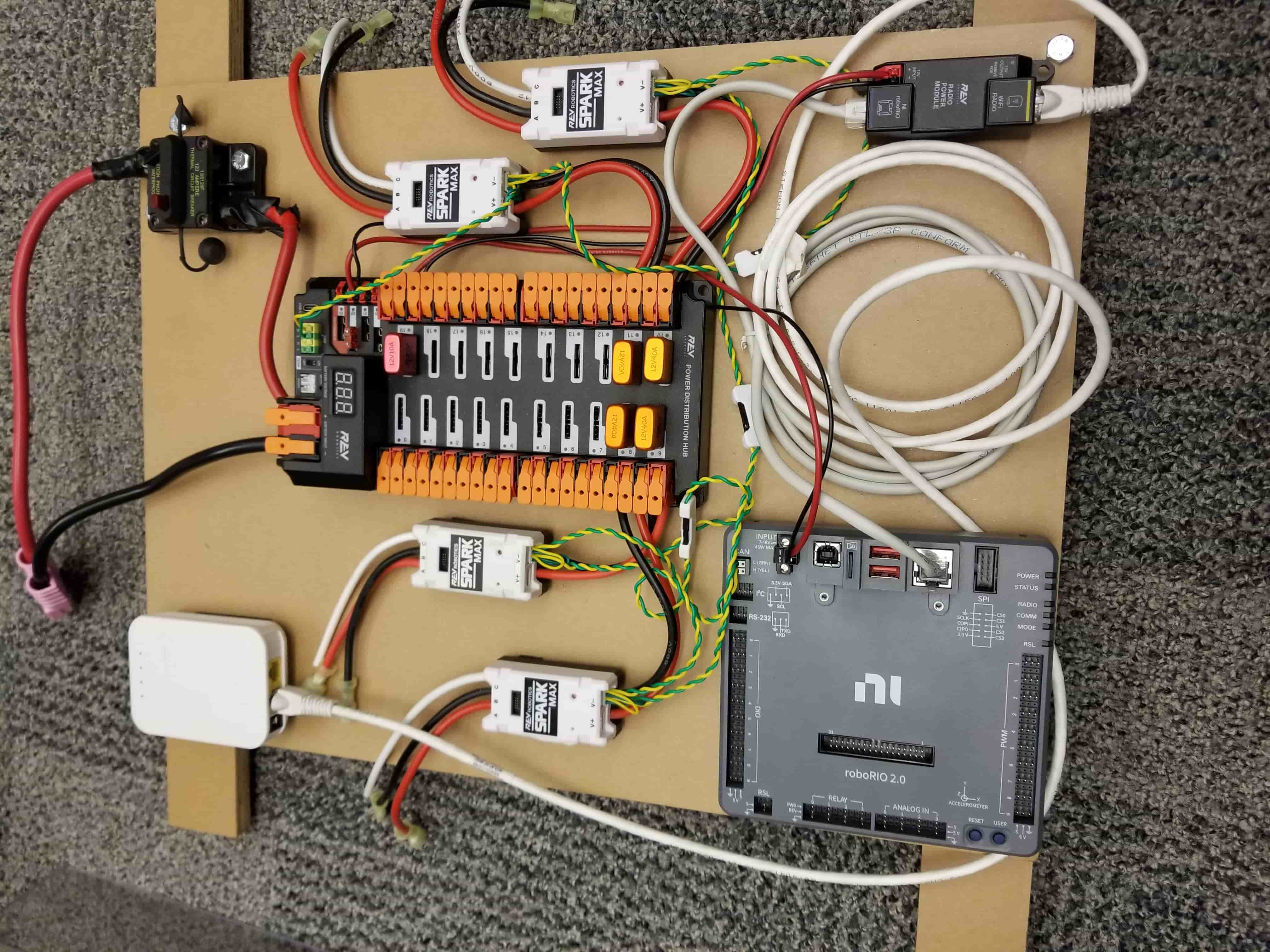
Electrical takes one 12 V battery and safely feeds a dozen or more motors, a computer, a radio and sensors, through wiring that has to survive a full season of hits.
The parts on every robot
Every FRC robot has the same core control system, so these are the first parts you’ll learn.
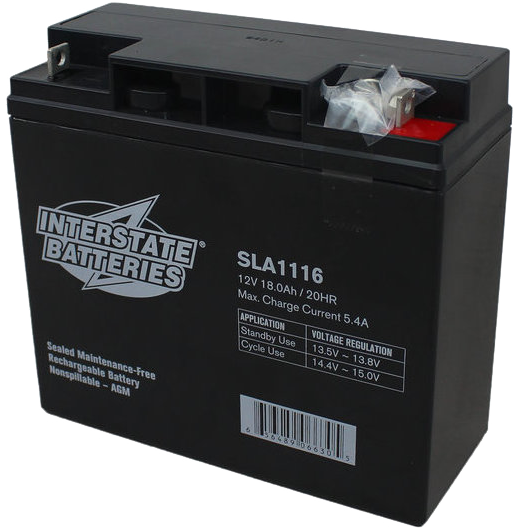
12 V battery
One sealed lead-acid battery, 17–18.2 Ah and about 13 lb. Teams bring a cart of them, charged between matches.
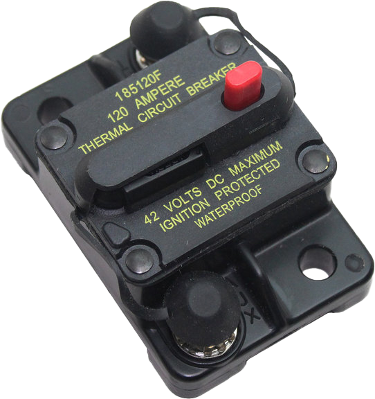
120 A main breaker
The robot’s master switch and its biggest fuse. It must be easy to reach from outside the robot.
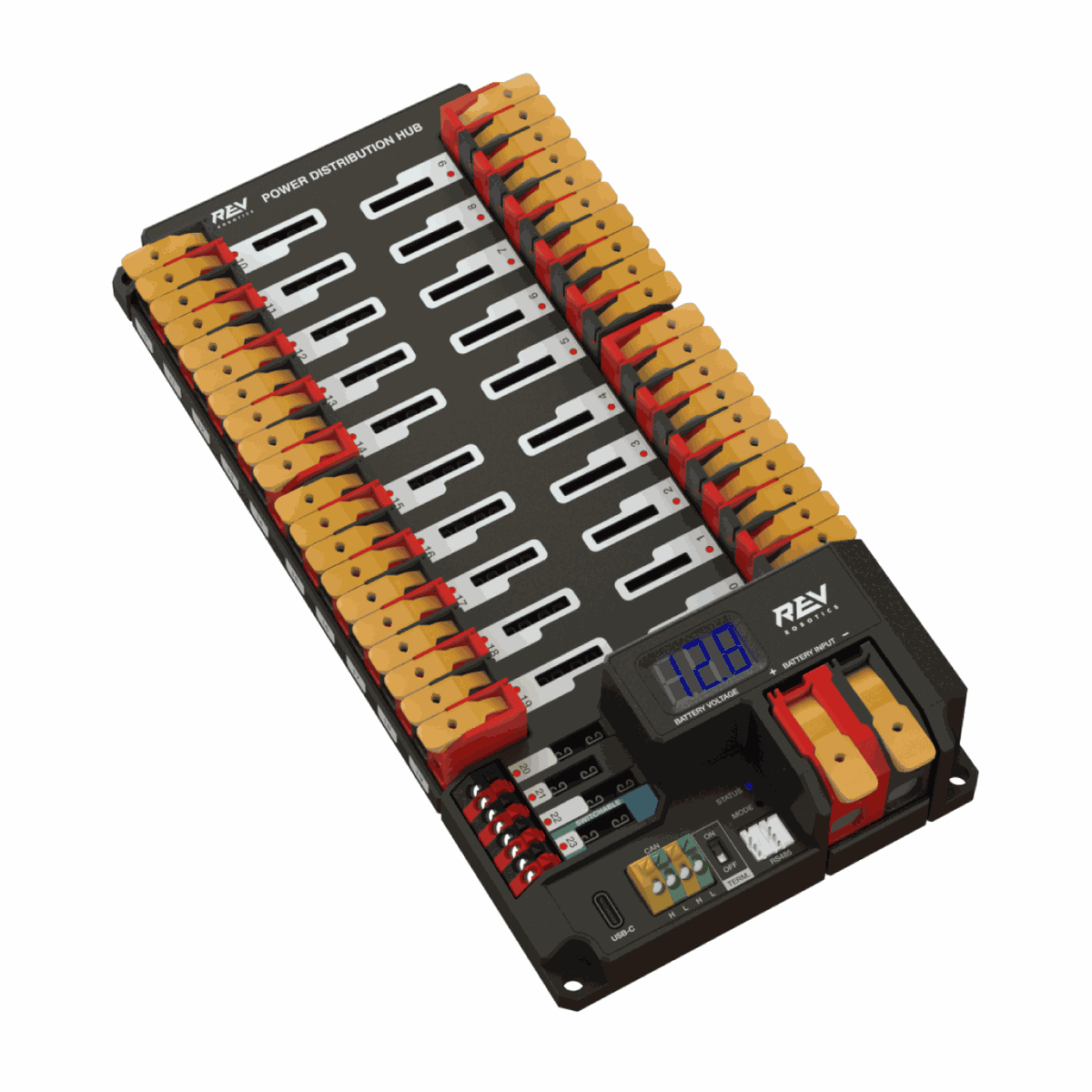
Power Distribution Hub
Splits battery power into protected channels, each with its own breaker, and reports current over CAN.
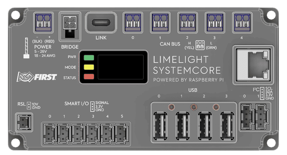
Systemcore
The new robot controller for 2027, replacing the roboRIO. A Raspberry Pi CM5 with five CAN buses, Smart I/O, USB and Ethernet.
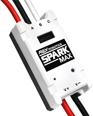
SPARK MAX
A REV motor controller. It turns small CAN messages into the high current that spins a NEO motor.
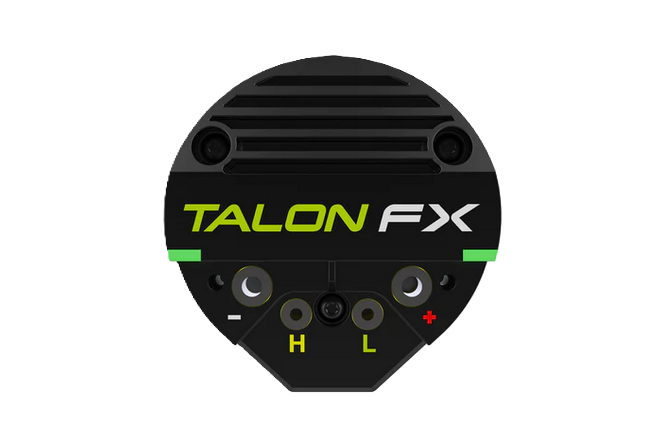
Talon FX
CTR Electronics’ motor controller, built right into motors like the Kraken X60. Power and CAN wire straight to the motor.
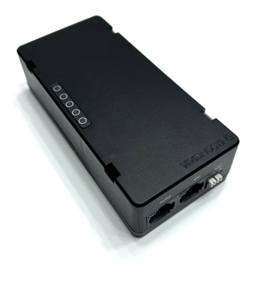
Robot radio
Links the robot to the field and the Driver Station over Wi-Fi. Powered from its own protected PD channel.
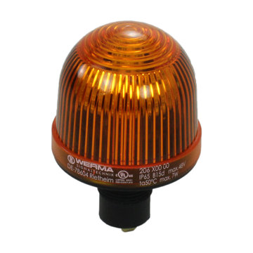
Robot Signal Light
Required orange light. Solid means powered and disabled; flashing means the robot is enabled and can move.
Thicker wire for bigger current
The breaker on a circuit decides the smallest wire you’re allowed to use. Too thin and it heats up under a stalled motor. AWG numbers run backwards: smaller numbers are thicker wire.
| Circuit | Protected by | Minimum wire |
|---|---|---|
| Main power path | 120 A main breaker | 6 AWG |
| Drive and mechanism motors | 31–40 A breaker | 12 AWG |
| Smaller motors | 21–30 A breaker | 14 AWG |
| Controller, radio, sensors | 6–20 A breaker | 18 AWG |
| CAN and signal wiring | Signal level | 28 AWG (22 typical) |
From the 2026 robot rules (R609 and R622). Always check the current season’s manual.
What wiring actually looks like
The steps you’ll do yourself, from bare wire to a board that’s ready for inspection.
 1
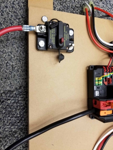
1Crimp, then bolt
Big 6 AWG wires get crimped copper lugs that bolt onto the main breaker. Tight, then check again.
 2
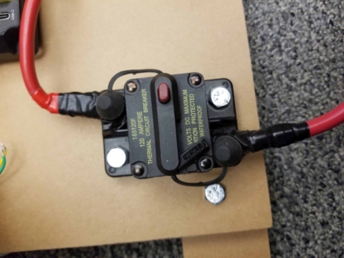
2Cover every terminal
Heat shrink and rubber boots over the breaker studs, so a loose bolt can’t short against the frame.
 3
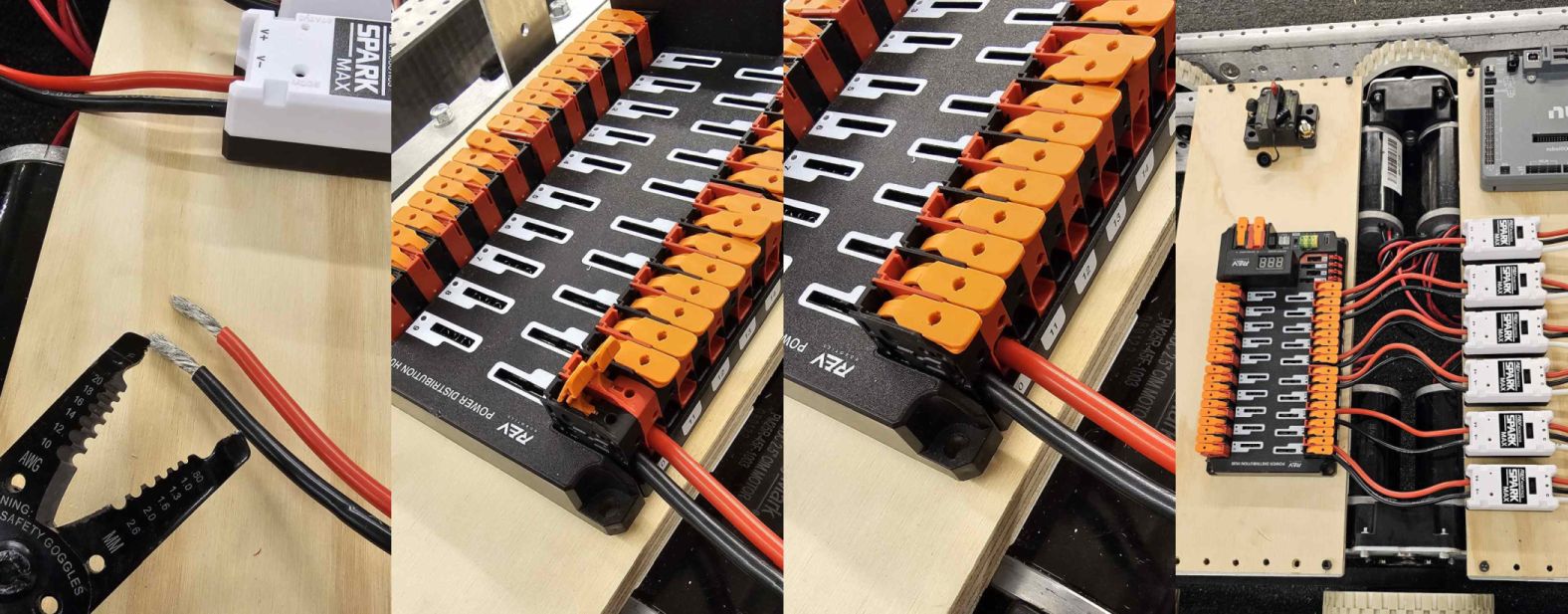
3Strip and lever in
Strip about 1/2 in of insulation, open the PDH lever, push the wire home and close it. Tug to check.
 4
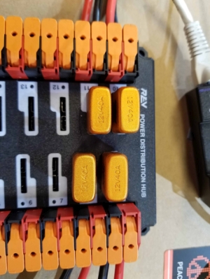
4One breaker per channel
Each motor channel gets a 40 A breaker. If a mechanism jams, its breaker trips, not the whole robot.
 5
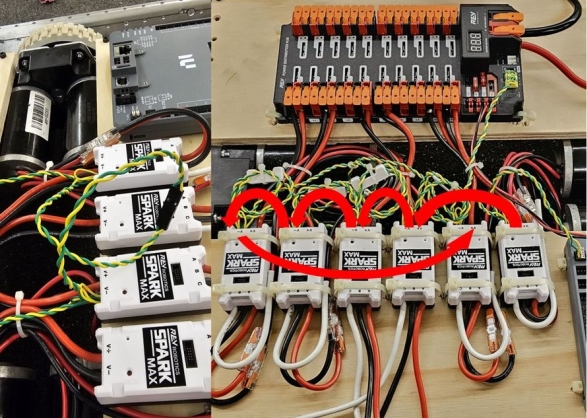
5Chain the CAN bus
Yellow and green CAN wires daisy-chain from device to device, with a terminator at each end of the chain.
 6
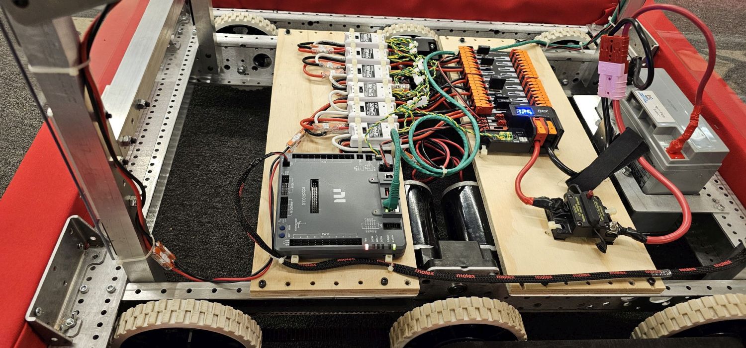
6Tie it down
Zip-tie runs to the board, keep wires away from moving parts, and leave slack so hits don’t pull them out.
Wiring that passes inspection
- Red is positive and black is negative, everywhere, no exceptions.
- Only one wire goes into each PD terminal. Splice before the terminal if you need more.
- The frame must never carry current. Inspectors check for more than 120 Ω between power and frame.
- Label both ends of every wire with the device and CAN ID.
- Pull-test every crimp and every lever connection.
- Leave a service loop, so a part can come out without rewiring.
Code that makes it all move
Programming connects the driver to the motors, and makes the robot drive itself during the autonomous period at the start of every match.
Driver
Xbox-style controllers
Driver Station
Laptop app: enable, modes, logs
Radio
Field Wi-Fi to the robot
Systemcore
Runs our robot code
CAN bus
Commands out, sensor data back
Motors
Controllers drive the motors
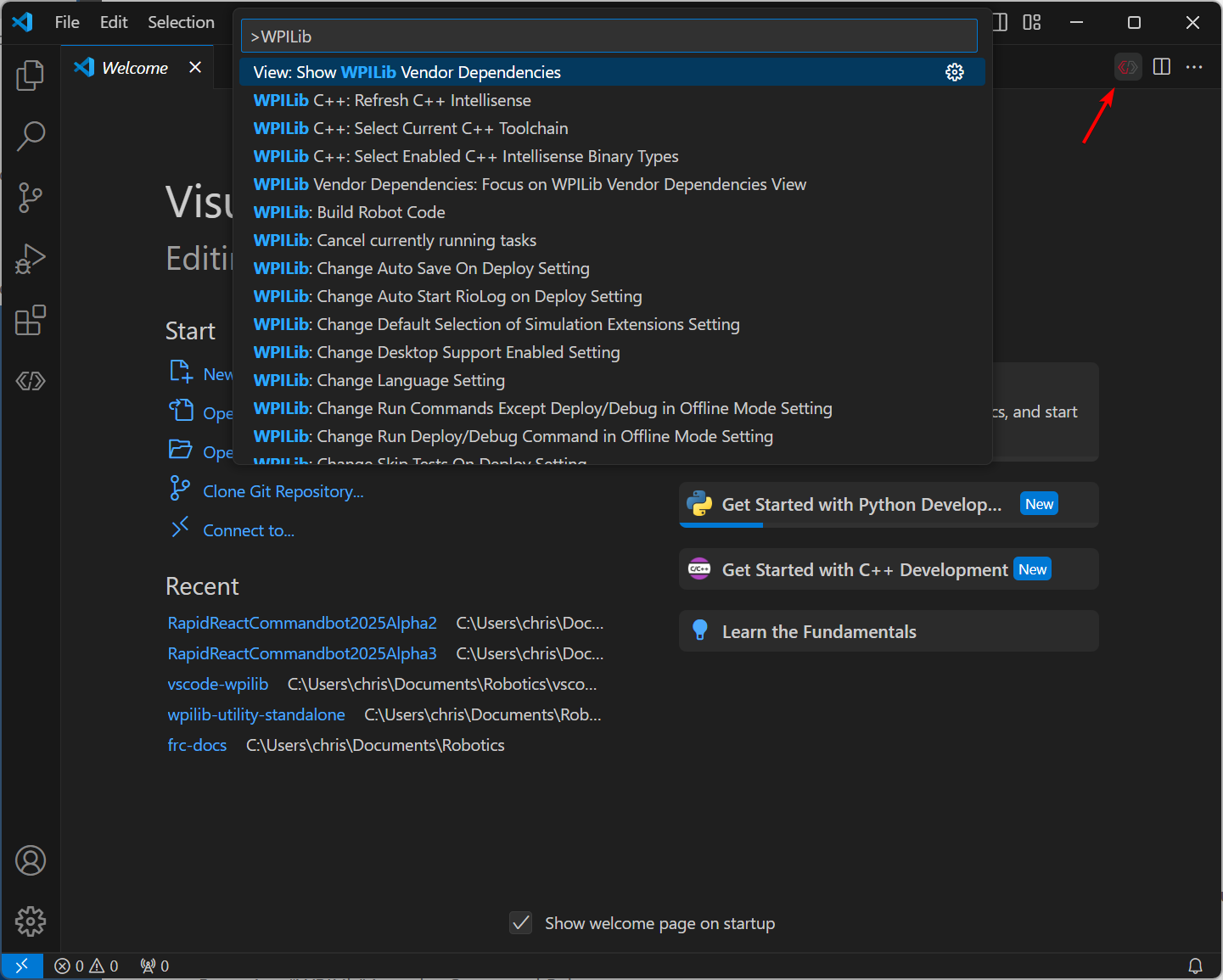
Java, WPILib and VS Code
FRC robots are programmed with WPILib, the official library that handles controllers, motors, sensors and math. It installs a ready-to-go copy of VS Code with commands to build, deploy to the robot and simulate.
We write Java, the most common language in FRC. WPILib also supports C++ and Python. Motor vendors add their own libraries: REVLib for SPARK controllers and Phoenix 6 for Talon FX.
Real robot code, simplified
Most teams use WPILib’s command-based style. A subsystem owns the hardware; a command says what to do with it; the RobotContainer ties buttons to commands.
public class Intake extends SubsystemBase {
  // "Motor" stands in for your vendor's class, e.g. SparkMax or TalonFX
  private final Motor roller = new Motor(5); // CAN ID 5

  /** Spin the rollers while the command runs, stop when it ends. */
  public Command run() {
    return startEnd(() -> roller.set(0.8), () -> roller.set(0));
  }
}public class RobotContainer {
private final CommandXboxController driver = new CommandXboxController(0);
private final Intake intake = new Intake();
public RobotContainer() {
// Hold the right trigger to intake; let go to stop
driver.rightTrigger().whileTrue(intake.run());
}
}
Subsystems and commands
Each mechanism is a subsystem that owns its motors. Commands are actions (“intake”, “raise to high”) that use subsystems, and only one command can control a subsystem at a time.
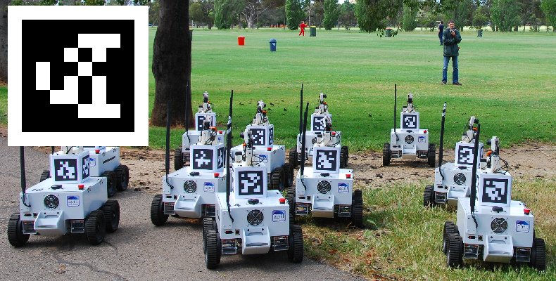
Vision with AprilTags
The field has printed AprilTags at known spots. A camera that sees one tells the robot exactly where it is on the field.
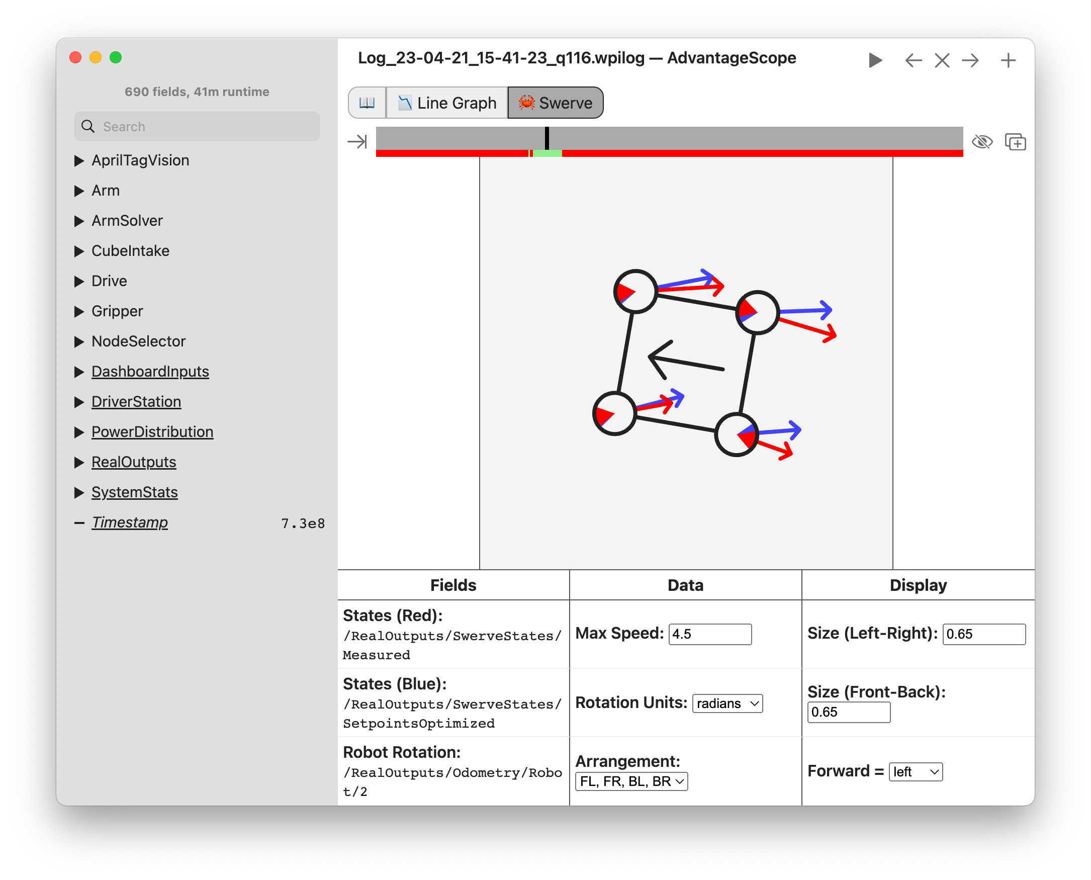
Logging and replay
AdvantageScope plays back every match log: what each swerve module was told to do and what it actually did.
Getting an arm to exactly 90°
Telling a motor “go” isn’t enough. A PID controller compares where the arm is with where it should be, every 20 ms, and pushes harder the further off it is. A feedforward term adds the push needed just to hold the arm up against gravity.
PIDController pid = new PIDController(0.08, 0, 0.002);

// Every 20 ms: how far are we from the target, and how hard should we push?
double output = pid.calculate(arm.getAngleDegrees(), 90);
arm.setVoltage(output + feedforward);
The robot loop
Robot code runs about every 20 ms: read sensors, decide, set motor outputs, repeat.
PID + feedforward
Control loops that move an arm to an exact angle and hold it there under load.
Odometry
Wheel encoders and a gyro track the robot’s position as it drives.
Autonomous paths
PathPlanner or Choreo draw a path; the robot follows it with no driver at all.
Simulation
Run the robot code on a laptop with a simulated robot before hardware exists.
Git & code review
Every change goes through GitHub, so nobody breaks the robot the night before an event.

Where we learn from
The same free resources every FRC team uses. Start anywhere.
WPILib docs
The official guide to FRC programming and the control system.
FRC game manual
Every robot rule. Read section 8 before wiring anything.
Onshape for FIRST
Free professional CAD in the browser for FIRST teams.
REV Robotics docs
PDH, SPARK MAX and NEO wiring and setup.
CTR Electronics docs
Talon FX, Kraken and Phoenix 6 software.
Chief Delphi
The FRC community forum. Someone has solved your problem before.
Want to learn this for real?
We teach all of it from the ground up, on a real robot, with mentors who do it for a living.